 Typica: Software for Coffee Roasting Operations
Roaster Configuration
Compatible devices for collecting roasting data
Typica supports a broad range of hardware with varying capabilities and prices.
Most new installations on roasters with thermocouples should consider using the Phidgets 1048. This currently has the best balance between quality of measurement and cost and it works on Mac, Windows, and Linux.
Roasters with RTDs are likely better served by using a panel display that can communicate with Typica through the Modbus RTU communications protocol. Many panel displays commonly used in coffee roasters have a model with that communications option. These will usually require an RS-485 to USB serial adapter. As long as your adapter has a driver for the operating system you want to use, this will work with Typica on Mac, Windows, and Linux. If you replace your panel display, you will want to be careful to ensure that the replacement part matches the physical size, power requirements, and features of the device being replaced that you want to continue using.
Other supported hardware options have more limited platform support.
| Device | Platforms | Notes |
|---|---|---|
| DATAQ DI-145 | Windows only | This hardware requires installing the DATAQ SDK. Note that this hardware does not take thermocouples directly and additional hardware may be required to use this device. It is not recommended to use this hardware for collecting temperature measurements (though it is possible with a signal conditioner to amplify the thermocouple signal), but it is well suited to logging control data of limited range and precision. |
| Modbus RTU Devices | Mac, Windows, and Linux | This option is recommended for most new installations that use an RTD. These devices are usually connected through an RS-485 to USB serial adapter |
| National Instruments NI USB-9211 | Windows only | This is an NI-9211 paired with an NI USB-9161. You will need to install NI-DAQmx Base 2.2 to use this hardware. |
| National Instruments NI USB-9211A | Windows only | This is an NI-9211 paired with an NI USB-9162. You will need either NI-DAQmx Base 3.6 or NI-DAQmx 9.6.1. Please install only one of those. Installing both will result in failures. |
| National Instruments NI 9211 paired with NI cDAQ-9171 | Windows only | You will need to install an appropriate version of NI-DAQmx to use this hardware. The author of Typica does not have this hardware for testing purposes, but there are several reports that it works. |
| National Instruments NI USB-TC01 | Windows only | You will need to install an appropriate version of NI-DAQmx to use this hardware. The author of Typica has not personally experienced problems using this hardware, but most reported issues that were ultimately determined to be due to faulty hardware or poor installation have involved this device. Which version of NI-DAQmx you need depends on the hardware revision of the device. If you get an error message about firmware being too new, you need a newer version of NI-DAQmx. |
| Phidgets, Inc. devices | Mac, Windows, and Linux | With the phidget22 library, Typica supports all Phidgets devices for monitoring temperatures. If you are using this on Linux, please read the documentation included with libphidget for important udev configuration information so that you will not need to run Typica as the root user. |
When using thermocouples it is possible to use thermocouple extension wire to connect data acquisition hardware such as the Phidgets 1048 or any of the supported National Instruments hardware without removing hardware already connected to that thermocouple or installing additional probes.
Please be aware that the inside of a roaster control panel often has high voltage electricity, so please disconnect power before opening your control panel.
It is important to make sure that all thermocouple wire connections are firm to ensure a good quality signal. The thermocouple extension wire must match the type of the thermocouple, otherwise measurements reported in Typica will be wrong. If you are unsure what type of thermocouple you have, you can determine this from the color of insulation on the two wires. Most coffee roasters with thermocouples use either Type J or Type K.
Compatible scales for presenting weight data
Typica is capable of displaying weight information from a connected scale while entering data before or after roasting a batch of coffee. This is known to work with the Adam PGL series and the Ohaus Defender series, but many scales that can be connected to a line printer through a serial port are likely to work with proper configuration settings.
Configuring Typica to work with your hardware
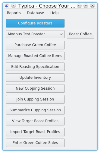
Typica works with a broad range of hardware and allows varied configurations to present information in a way that's appropriate diverse roasting environments. This flexibility to in data collection and presentation comes with a requirement to configure Typica before attempting to roast coffee. In the first window that appears after opening a configuration file, you will find the "Configure Roasters". This is where all details related to data acquisition and presentation can be configured. This includes not only data acquisition hardware but also annotation controls that can be used to mark events of interest during the roasting process, various kinds of timers, calibration options, rate of change series, roast profile translation, graphing options, and diagnostic logging.
Please note that configuration options will not be available for some types of hardware unless software Typica requires to communicate with that hardware is installed. When configuring Typica to work with data acquisition hardware, it is recommended that the computer is connected to that hardware.
If you are using Typica at a computer not connected to a roaster for things like accessing reports or entering purchase data, you do not need to configure a roaster.
It is unlikely that you will have all supported hardware connected at once. Please feel free to skip over sections on configuring hardware you do not have.
Setting up your first roaster
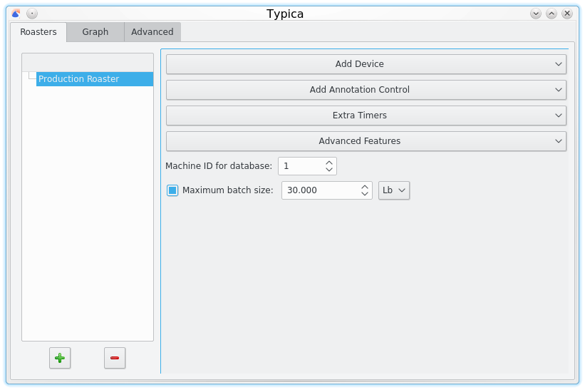
The first time you use Typica, you will not have a roaster configured and will not be able to use data logging features until this is configured. The first thing you will want to do is click the green + button at the lower left. This will add an item to the tree view on the left representing that roaster. You can double click on "New Roaster" to change the name of your roaster to something more descriptive.
Clicking on the roaster item you will find two things that can be configured as well as controls for adding additional features to your roaster configuration.
Machine ID for database
This is an integer used to uniquely identify the coffee roaster in the database. It should be different for every coffee roaster you intend to use, otherwise it will be impossible to distinguish which batches of coffee were roasted on which machine.
Maximum batch size
This is an optional feature. If enabled and a maximum batch size is specified, any attempt to roast a batch of coffee with more green coffee than the maximum capacity of the machine will present a warning. Note that it is still possible to disregard the warning and roast an over-capacity batch. The feature is not intended to prevent deliberate over-loading, but warn about potential data entry mistakes.
Devices
Clicking on Add Device will show several options. If you do not see an option appropriate for the hardware you intend to configure you may need to exit Typica and install additional software required to use that device.
Modbus RTU Device
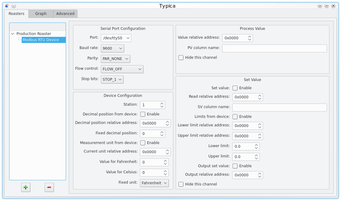
This adds a "Modbus RTU Device" node to your roaster in the tree view on the left. This configures Typica to use a device that communicates using the Modbus RTU protocol. There are several limitations on the devices that can be used with this and this will be removed in a future release. If you do not require sending updated process values to the device from within Typica, consider using ModbusNG Port instead which supports reading from multiple devices on a bus, does not limit the number of addresses you can read from, and supports devices that present measurements as floating point values in addition to fixed point integers.
Clicking the "Modbus RTU Device" item in the tree on the left presents a number of configuration options.
Serial Port Configuration
The controls in this panel control your serial port configuration. The configuration needs to match that of the connected device.
Device Configuration
This presents a number of options for communicating with the device and interpreting measurement data.
The station number is sometimes referred to in device documentation as the slave ID and needs to match the configuration of the device you are communicating with.
Decimal position from device indicates if you want Typica to ask your device how many decimal places the measurements have. If this is enabled, you will need to provide an address where that information can be queried. See the communications manual for your device to discover this value. Alternately, you can specify a fixed decimal position. This should be an integer representing the number of digits after the decimal point.
Measurement unit from device indicates if you want Typica to ask your device which measurement unit is in use. If this is enabled you will need to specify the address where that information can be queried. See the communications manual for your device to discover this value. You will also need to provide what numbers the device returns to indicate Fahrenheit or Celsius units. Alternately, you can specify a fixed unit.
Process Value
Here you must provide the address where the measurement you want to read can be queried. The column name should be a short piece of text that is unique across all column names on the same roaster. This is used as the table header for the column where measurements on this data series are displayed and is also used if you need to refer to this data series when configuring other features. The Hide this channel option will result in measurements not being displayed. This is useful if you want to apply a calibration adjustment to this data series.
Set Value
It is optionally possible to allow Typica to write values to your device. If the set value is enabled, you will need to provide an address where the current set value can be read. This allows you to use controls on the device to change the set value and show the updated values in Typica. The column name should be unique across all column names on the same roaster. Values to write will be bound to a range. If Limits from device is enabled you can specify the addresses where those limits can be queried from the device, otherwise you can specify fixed limits yourself. If Output set value is enabled, you will need to provide an address where this value should be written to the device. This will provide a control where you can directly type new set values in Typica and have that value sent to the device. This channel can also be hidden if you do not want to see the information in the table or graph.
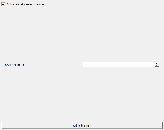
DATAQ SDK Device
This allows communication with the DATAQ DI-145. If you only have one device supported by the DATAQ SDK connected to your computer, the easiest way to configure this is to just select "Automatically select device". If automatic device selection does not work reliably with your installation, it is also possible to specify the device number directly.
After configuring the device, you will need to click the Add Channel button as many times as the number of inputs you intend to use on the device.
You can double click the channel item in the tree view on the left to change what the channel is called. This text is displayed above the indicator for the channel while roasting coffee.
This hardware requires some initial manual calibration. You should have this connected to your roaster before attempting to configure Typica to communicate with the device. If you intend to read temperature measurements, chances are good that you have a signal conditioner amplifying and linearizing a thermocouple signal. Initial calibration may be easier if you have a thermocouple simulator available to provide calibration signals through the signal conditioner.
When configuring each channel you will find several options.
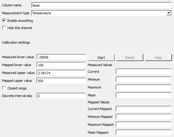
Column name
This should be a small amount of text that uniquely identifies a channel on the roaster. It is also displayed in the table header.
Measurement type
This can be set to either Temperature or Control. If this is set to Temperature, the mapped values used for calibration should be in degrees Fahrenheit and measurements will be treated as temperature measurements. If the measurement type is set to Control then Typica will interpret that as a unitless measurement and will not apply unit conversions if you prefer to have temperature measurements displayed in degrees Celsius while roasting.
Enable smoothing
The DATAQ DI-145 features a very low resolution analog to digital converter with substantial noise and poor channel isolation. When reading something like a percentage fuel setting or an airflow position, this is usually not a problem, however with temperature measurements you may find that your signal conditioner presents temmperatures likely to be recorded during roasting in a narrow portion of the full scale range of the device. In that case, smoothing is essential to remove excess noise from the signal, especially if you intend to also have a rate of change series connected to this channel.
Hide this channel
If you do not want to see measurements from this channel, you can hide it. This is most useful when an additional calibration series is connected to the channel.
Calibration settings
The DATAQ DI-145 reads signals in the range of -10 to +10V but you will most likely want to convert that to something more meaningful. For example, suppose you have a channel that reads the fuel setting and you would like to express that such that 0 is your minimum fuel setting and 100 is your maximum fuel setting. If the device is connected, you can set your fuel at minimum and press the Start button to see what values the device is reading. You can use the measured values to set a value on the left for measured lower value and 0 for the mapped lower value. Then you can increase the fuel setting to maximum, press the Reset button, and use the measured values to decide on a value to set for your measured upper value and mapped upper value. When all four of those settings are entered, you can see what the device is measuring and how Typica will interpret that. Two additional options are also available. If you select Closed range, Typica will only produce values in the mapped lower to mapped upper range even if the measured values go outside of that range. You can also set a Discrete interval skip. If this is 0, no rounding will occur. Otherwise, the values produced by Typica will always be a multiple of this value.
Historical Note
This hardware is supported in Typica because Diedrich Manufacturing provided it as a communications option on their roasters and wanted Typica to work with that. The video here shows how this hardware was connected on an IR-1 Profile Lab Roaster and how this was configured in Typica.
Due to the need for a power supply and other additional hardware to produce signals in the range this device measures, the DATAQ DI-145 is not generally recommended unless you are using a roaster that was built with the intention of connecting a device like this.
The poor channel isolation and low resulution of the ADC also make this poorly suited for recording temperature data, though it works very well for control data of limited range and precision.
National Instruments devices

Some National Instruments devices can be used by selecting NI DAQmx Base Device while others require NI DAQmx Device. The NI USB-9211A can be used with either but only one of NI DAQmx or NI DAQmx Base should be installed. Clicking the newly created item in the tree on the left gives you the option to add a supported device. Note that if you are using the NI 9211 paired with a cDAQ-9171 you should select NI USB 9211A as the only configuration difference between these devices is a different device name.
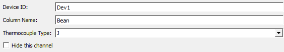
NI USB TC01
Unlike other supported National Instruments devices, the TC01 only supports a single thermocouple channel. As such, the device and channel are configured on the same item. You can double click the item on the left to change its name and that will appear above the temperature indicator for that channel.
Device ID should be the name of the device and is likely to be something like "Dev1" (without the quotes). The Column name should be a small piece of text that is unique to all channels on this roaster. It is used by other features that need a reference to a column name and it also appears in the header of the table view. Thermocouple type should match the type of thermocouple you are using. Hide this channel can be used to not display measurements from this device.
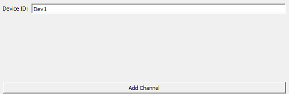
NI 9211 based devices
All supported NI devices other than the TC01 are configured in the same way. You will need to specify the device ID and click Add Channel as many times as the number of channels you intend to use with that device.
While this hardware supports up to four thermocouple channels, the sample rate decreases as more channels are added. It is recommended to use no more than three.
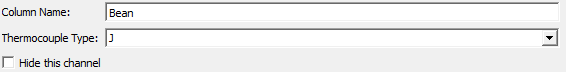
Each channel must then be configured. The item in the tree view can be double clicked to change the text that will appear above the channel indicator.
The column name should be a small piece of text that is used to reference this channel from other parts of the configuration. It will also appear in the table view as a header. This text should be unique for each channel on the roaster.
Thermocouple type should be set to the type of thermocouple connected.
It is also possible to hide the channel.
Phidgets 1048
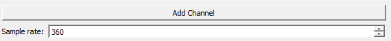
Choose Phidgets 1048 from the Add Device drop down. Note that this will only appear if the required hardware interface library is installed. This will create a new item in the tree on the left called "Phidgets 1048".
Clicking the newly created item allows you to add channels and configure the sample rate for the device.
Sample Rate
By default the sample rate is set to 360, which represents collecting approximately 3 measurements per second. Setting this to a smaller value will increase the rate at which measurements are collected by Typica while larger values will decrease that rate. Please note that this default is not based on any rigorous evaluation of what value works best for coffee roasting and this default may change if anybody does that research.
Clicking on a Channel item in the tree on the left will allow you to configure the details of the channel.
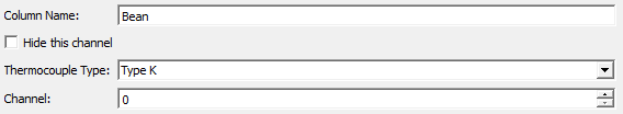
Column Name
This should be a small amount of text that uniquely identifies a channel on the roaster. It is also displayed in the table header.
Hide this channel
If you do not want to see measurements from this channel, you can hide it. This is most useful when an additional calibration series is connected to the channel.
Thermocouple Type
This should be set to match the type of the thermocouple connected to this channel. Types K, J, E, and T are supported by this hardware.
Channel
This is the hardware channel number.
Other Device
Selecting "Other Device" from the Add Device drop down allows Typica to support additional hardware by allowing you to write script code to implement the communications protocol used by that hardware. It is almost always better to implement support for additional hardware within Typica's C++ code instead and the use of "Other Device" is not recommended.
Annotation Controls
Typica supports several ways to add additional notes to your roasting data. One of these is through the use of annotation controls. These controls associate additional information with a particular time during roasting. When using any of the controls that require manual activation, please consider carefully if the tradeoff of additional operator effort for additional logged data is worthwhile.
Annotation Button
The annotation button provides a control that can be used to add pre-defined text as a note. This is best for details that you intend to log which are predictable but not automatically detectable.
Counting Button
A counting button can be used to add text that contains a number that increments every time the button is clicked. This is commonly used when pulling a series of samples to evaluate from a single batch of coffee.
Numeric Entry
This creates a control for adding an annotation which contains a number that the operator can control. Some people use this for things like noting changes in fuel pressure on installations where this cannot be logged automatically.
Free Text
This allows free form comments to be added.
Value Annotation
This allows annotations to be created automatically when specific values are recorded on a data series.
Extra Timers
Typica always presents at least one timer showing the amount of time that has elapsed since the start of the batch, but additional timers are also available.
Cooling Timer
The cooling timer sets itself to a specified time and counts down at the end of a batch. This can be used to inform an operator that the previous batch of coffee is likely cooled and can be removed from the cooling bin.
Range Timer
You may want to record the amount of time in an interesting portion of the roasting process. If you want to control when this starts or stops manually or if there is only one range that you are interested in, a range timer is a good choice. If you have multiple ranges of interest, consider using a multi-range timer instead.
Multi-Range Timer
The multi-range timer splits a roast into multiple consecutive regions at specified temperatures and reports the duration of each range at the end of the batch.
Advanced Features
Some features that should be configured separately for different roasters do not fit into a feature category. These are grouped together under Advanced Features.
Linear Spline Interpolated Series
This is used for calibrating measurements among multiple coffee roasters. Measurement differences among different machines tend to be nonlinear over the range of temperatures measured in the roasting process. By using linear spline interpolation, you can have as many calibration segments as required to produce a high quality mapping over the entire maesurement range.
Source column name
This should be set to the name of the column associated with the hardware channel. Once you are satisfied that your calibration mapping is acceptable you may want to hide the source column. Doing so will not impact the operation of this feature.
Destination column name
This is a new column name which should be distinct from any other column name. The output of this interpolation series will go to that column.
Mapping data
This is a table of inputs and outputs which define the knots of interpolation series. Data outside of the mapping bounds will be extrapolated along the slope of the nearest segment. Note that at least two rows are required. If you require a fixed offset, this can be produced by specifying any two input values and providing an output value that is different by a constant amount.
Profile Translation
Differences in the earliest portion of the roast prior to the start of chemical change usually have little to no observable difference in the finished coffee, but compensating for differences in that earlier portion of the roast after the start of chemical change can produce very significant differences in the taste of the coffee. Profile translation allows you to shift data from the current batch relative to a roasting plan along the time axis so that the two data sets appear to match at a given temperature. Use of this feature often results in measurable improvements in roasting consistency.
Column to match
This specifies a column name which must exist in both the currently configured roaster and saved batch data you wish to use as a roasting plan.
Unit
This specifies the unit the translation point is specified in. Note that the currently displayed unit while logging has no affect on this feaature.
Value
When the column to match ascends through this value, profile translation will be triggered.
Rate of Change
The rate of change of the bean temperature can be used to more quickly detect and respond to changes in the roasting process. If you want to see this information graphed, you will also need to click on the Graph tab to configure a secondary axis for rate of change data by enabling Graph relative temperatures and configuring a set of grid line positions.
Primary series column name
This is the column name of the data series used to calculate the rate of change.
Cache time
This defines the size of the window used for rate of change calculations. Typica stores all measurements collected within the given number of seconds and produces a linear regression across those measurements. This produces a smoother and more usable graph while remaining responsive to real changes. The larger the cache time, the slower Typica will react to change but the smoother the rate will appear. Smaller cache time values will be more responsive but may expose noise in the input data.
Scale time
A rate of change is a fraction expressing a change in temperature divided by a given amount of time. Scale time is the amount of time assumed for the denominator of this fraction.